Dust Prevention

Image result for haboob in phoenix

My observatory is in the Arizona desert. As such we get a tremendous amount of dust in the air.

  1. I’m sure there is a large amount of dust suspended in the air in general.
  2. We get occasional high winds which pick up a lot of dust as they blow across the desert.
  3. We get occasional dust storms which are amazingly dense dust – you can’t see 3 feet in front of your face. Apparently “dust storm” is politically incorrect, so the media has taken to calling them “haboobs”. The image above shows a storm coming across the desert. Notice the mountains in the background; that wall of dust is BIG.

I spent 4 days cleaning the observatory. The dust is tough to get up; it is thick and deposits like mud (probably electrostatically charged). You can’t use a Swiffer or dust cloth – at best that just smears the dust around. You have to use rags and water to pick it up.

I have implemented some anti-dust strategies which I hope will help:

  • I made a cloth skirt which goes around the outside of the dome. The skirt is about 6 inches long, hanging off the rotating dome and dragging on the roof. I’m hoping this will provide another barrier to dust coming in that way. The cloth has two ropes sewed into the edges. The top rope allows the cloth to pull tightly against the plastic band holding it against the dome, making a tight seal. The lower rope weights the bottom edge of the skirt to make sure to drapes down onto the roof.
  • I plan to install some weatherproof sealing against the edge of the shutter. The upper shutter in particular does not seal tightly when closed.
  • I put cloth drapes over the computer table and various equipment cabinets. I also put a drape around the base of the mount. When I need something I just lift the drape (to get at a tool chest, for example). I put Velcro on the computer drape to hold it on the monitor – it kept sliding off to the back.  Now, every so often I will just need to wash the drapes.
  • My electronic cabinets were designed for upstate New York, where I encountered serious insect invasion issues. The cabinets have open front and back doors for air flow, with two layers of screen keeping out bugs. I added a cloth layer to the doors to hopefully keep out dust while still allowing air flow.
  • I changed the scope Park position back to pointing the scope downward. I will need to change this in the summer; the heat causes grease on the Celestron Edge baffling to drip onto the corrector plate. However, the rest of the year I hope that less dust will settle on the telescope glass if it is pointing down.

New FSQ106, maintenance

FSQ

Have obtained a new-to-me FSQ106EDIII. After some false starts I have the adapters from OPT and Texas Nautical. Built another bracket to attach the EZFocus motor.

While testing the focuser for slippage the wall wart died. Very hot, no voltage. Replaced it with a cable to the old 12V power supply, seems to be working now.

Odd issue – while running the VCurves and ACP Focus Offset script, I notice that the focus position seems to be consistently changing. If I run multiple focus runs in a row, as quickly as possible, the resulting position seems to shift by about 35-40 focuser tics. This shift is probably roughly the size of the crtical focus zone.

So, when Focus Offsets runs, it seems like the focus position of each filter is off by n*35 tics. When HAlpha comes up with an offset of 189 tics, it may actually be off by 140 tics!

I don’t know what is causing this shift. The scope certainly doesn’t shift temperature that fast. I thought maybe the focuser was slipping, but measuring the position of the camera with a dial caliper shows to slippage. I ran the focuser back and forth 5 times (1000 pulses each way) and it ended up back at the correct position each time.

I did find that the backlash was off; I changed from 200 to 500 pulses. I will re-run the Focus Offset script again.

Maintenance

Updated ACP to 8.1, including updating the web system.Cleaned up the web menu system a bit, added a couple of items (AstroCalc).

Updated FM to 4.1.0.44.

Single Star versus Multi-star guiding in Maxim

I have always used single star guiding in Maxim. However, in Maxim version 6 they implemented multi-star guiding. I wanted to test the multi-star compared to the usual single star.

Basic conclusion: multi-star guiding does not show an appreciable gain in guiding precision. There may be other reasons for using it; perhaps it is more robust somehow, perhaps it is better in poor seeing conditions? I was unable to test these issues; I just looked at guiding precision.

The clear difference in guiding was better seeing as the night went on. The initial guiding started after astronomical twilight. Both guiding techniques improved significantly as the evening went on. I often see this trend when using the Subframe Selection script in PixInsight; as the evening wears on the FWHM moves steadily downward.

Data Collection

I imaged several 5 minute exposures, binned 2×2, using the Edge 11/STF8300M setup. The guider is the integrated STi in the 8300 package. This setup has an image scale of 0.80 arcseconds per pixel.The STi is binned 1×1. The same calibration settings were used for Single star and Multi-star guiding.

The images were well guided; I happened to have better seeing this night. In poorer seeing I typically see larger fluctuations in the guide errors. It may be that multi-star guiding would help more in poor seeing.

I used three targets: one in the Milky way to ensure a good number of guide stars for multi-star guiding, and two targets with few guide stars. The images are not calibrated or stacked, although the Maxim Filter tool was used to remove hot and cold pixels.

I measured the guiding accuracy using the graph tool in Maxim. After guiding has been started I clear the graph and let it run for 30-50 points. I then read the RMS X and Y errors from the graph, clear the graph, and repeat. In each situation (single or multi star guiding, a particular target) I repeat this process 5 times and average the results.

I also measured the FWHM of the resulting images using both CCDInspector and PixInsight. Their results were essentially the same, which is reassuring.

Results

rmsguideerror

This shows the RMS guiding error as the evening went on. The green points are using single star guiding, the blue use multi-star.

In the first half of the graph the RMS errors are more variable. In the second set of three readings the guiding has settled into a more consistent pattern.

fwhm

These are the FWHM measurements from PixInsight (in pixels). The first image in particular was poorer (3.3 px * 0.8 as/px = 2.64 as. The last six images are around 2.4 arcseconds.

Dueling Air Conditioners

I installed a small 8000 BTU window air conditioner in the dome several years ago to keep the dome cool during the summer. I am concerned about the dome getting so hot in our 115 degree heat that the electronics will be damaged (computer, power controller, mount, …).

As described in an earlier entry, I built an Arduino based temperature probe and wrote a little program ACCycle to turn the air conditioner on and off.

InitialCool

This has been working OK, but the AC is clearly unable to keep up. As the image above shows, no air conditioning would generate the red line. The orange line shows the typical response to the single unit coming on; it lowers the temperature in the dome by 5-10 degrees, but otherwise follows the ambient.

So, I bought a second 8000 BTU unit. This one is a portable unit with the big hose that exhausts out the window. The blue data shows the result of both units turning on – the temperature immediately lowers back to the target 85 degrees.

Not So Simple

First, it is clear that the two units together work very well. Now, instead of seeing the dome temperature follow the outside temperature (but a few degrees cooler) I can see the AC units kicking in and bringing the temperature back down to 87. I have it set to start cooling at 90, stop at 87. In the image below the dome temperature (blue line) rises steadily in the morning. About 8:30 it hits the upper limit of 90, at which point the two units kick on. They quickly cool back below 87, at which time they shut off. The units cycle until about noon; at that point the heat is enough that the units stay on steadily until about 5:00 PM, when it starts cycling again.

TwoACunits

But –  I am encountering power problems, which I have never had to think about before.

Surge Protector Limit

To start, my Power Controller is plugged into a big surge protector, which in turn is plugged into the wall. When the two AC units are turned on, the power exceeds the surge protector limit. The surge protector shuts off, including power to the computer and everything. I have to reboot the system and start everything again. Doesn’t happen every time, so I am apparently close to the limit of the surge protector.

Power Controller Problem

So, my next step is to plug the power controller directly into the wall, bypassing the surge protector. In addition, the controller has an “A” and “B” side, each allowing 15 amps. I had been running both AC units from one power cord on the “B” side. Now I plug one AC into the “A” side and the other into the “B” side.

Well, it is better, but every so often ACCycle turns the AC on but they don’t actually turn on! I think the surge through the Power Controller is problematic somehow. I have trouble reproducing the problem, but is seems to happen a couple of times a day. Unfortunately, it can end up in a state where the AC is off, but ACCycle thinks it is on. Thus, the dome keeps heating up.

Shadow AC

Next approach – get around having both units turning on simultaneously.

One approach would be to put the two units on separate ports in the Power Controller and have ACCycle control both units. However, I don’t have any extra ports in the Power Controller. I could buy another controller:(

Instead, I put one unit on a manual timer on the wall socket. This timer will turn on the AC at 9:30 in the morning and turn off at 7:30 at night, after sundown. At this time of year there aren’t any days where cooling isn’t needed, so this is reasonable.

Now ACCycle only controls the second unit. It only kicks in when the first unit cannot handle the load. Both units don’t necessarily run, and they don’t kick on at the same time. In the image below the first unit started at 9:00 AM. It was a cooler day (only reached 101) so the second unit wasn’t needed until late in the day about 4:30 PM. It kicked in briefly when the temperature got above 90 and quickly brought it under 85, at which point it wasn’t needed any more.

DoubleAC

Weird Diffraction Spikes Part 2

The saga comes to a close…

Celestron Help

After talking to the Celestron Rep (Will) it sounds like I missed something when inserting the secondary. There is a small set screw on the inside of the secondary which needs to fit into the slot on the secondary housing (the tube passing through the corrector plate).

Will also made a couple of other points.

  1. the slot in the secondary housing, the mark on the secondary, and the set screw should all point at 1 o’clock. That is how his system is set up.
  2. The secondary housing is not glued, it is just tight. Apparently it is very easy to bind the threads, the tube can flex. He described a couple of ways to try and tighten it so the housing is stable.

I retried inserting the secondary, making sure the set screw is positioned correctly. It seems to fit better.

Voila! Now I can focus correctly. I then worked on collimating, and was able to make that work.

I then tried the collimation tool in CCDInspector; I’ve owned this tool for awhile but never tried this piece. It was a little confusing at first. There are various colors which I anticipated were trying to tell me stuff, like which direction to turn the screw – apparently not.

One very helpful aspect – I connected Maxim to the ACP Telescope hub and put in the correct image scale (0.39″/px). This enables the function in the right click menu on an image to re-position the scope to point to a particular spot. This makes it much easier to recenter the scope after each adjustment.

After I got the hang of it, I was able to get the collimation to less than 5″, perhaps under 3. At that point the seeing and clouds were preventing any improvement. The collimation is clearly better than what I used to get using my manual method. A focusing run shows very symmetric patterns on the stars.

Starizona Help

Now that I am correctly inserting the secondary, I still need to get the secondary housing firmly attached to the corrector plate. Before starting with Will’s suggestions I called Dean at Starizona to get his thoughts. He had some other techniques I could try to tighten the housing.

In the end, I decided to bring the OTA to Starizona rather than risking messing up the housing. I’m glad I did. Dean was very helpful and knowledgeable. It was great just seeing him do some of the various tasks – there are a lot of things one hears about, and that I have done, but don’t really know how to do exactly.

Dean pulled the corrector and managed to get the two parts of the housing separated. He then replaced the paper (almost invisible) gaskets with a rubber type, then re-installed the housing in the plate.

He then cleaned the corrector, doing a much better job than I had. Very interesting watching his technique.

Now came a possibly controversial part. There are several threads out there about whether the corrector should be moved. In particular, a long series of posts on Cloudy Nights which concludes that the plate should not be moved from the factory setting, and should not be physically centered (the factory setting is the correct optical centered position). Dean disagrees – after putting the corrector back in, he adjusted the position to get the secondary/housing/corrector centered by looking down the OTA from 6-12 feet. He says he has convinced Celestron they are aligning their correctors incorrectly? They came out and visited to see how he does it…

Also, Dean positions the secondary and housing to point at 3 o’clock instead of 1 o’clock.

Anyway, he did his alignment which included very slightly shifting the corrector. He also collimated using an artificial star. He clearly has a very experienced eye.

Mystery Solved

The source of the trails on the corrector was identified by Dean. Apparently when it gets hot the grease on the primary baffle can bleed some of the more volatile components. Dean showed me the trail running down the primary baffle; clearly the same fluid on the corrector plate and under the edges of the plate.

I have (cleverly, I thought) defined the scope’s park position to have the OTA pointing down. The idea was to keep some of the Arizona desert dust from collecting on the corrector plate. This was a bad idea, since it allows the grease to drip onto the corrector.

If the OTA is pointed up, the grease will run down into the back of the OTA. Apparently this is not a problem.

Subsequent Collimation

After I got the OTA remounted, rewired, and balanced I was curious to see how Dean’s collimation was, as per the CCDInspector tool. It was pretty good, about 14″. Certainly better than what I would get (about 50-70″). I then played with it and managed to get it to 1.5″. At that point the direction line is flitting around quite a bit, but generally less than 1″. Wow!

Now I have centered the focus position near 3500 on the Optec, locked the mirror down, and started re-running VCurves. I’m eager to see how the overall performance of the system might be affected.

Weird Diffraction Spikes

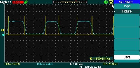
For a little while I have been getting strange diffraction spikes from the Edge 11/STF8300M system, as seen in the sub below. The brighter stars have 2 diffraction spikes, when they should not have any (no support vanes to cause them). The two spikes are at a 10-20 degree angle from each other.TestRedFilter15Min

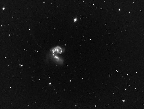
The crop below shows is zoomed in a bit to show the spikes better:

CropSpikes

I have been working on my Dome driver for the Arduino controller; I thought these were due to the OTA not pointing accurately out the dome’s slit. However, when I got around to checking, the OTA was in fact pointing precisely out the slit.

SnailPath

Big trails seen on the left. Two trails are at an angle, leading to the observed diffraction spikes.

So, I went out and started to look at possible causes. Right off the bat, when I looked at the corrector plate, there were 2 “trails” on the inside of the corrector plate! It looks like a snail crawled down the plate. The trails are at an angle, matching the angle of the diffraction spikes.

SnailWallsIn addition, there are a couple of trails on the inside of the tube, along with a blotchy area. These look like liquid has somehow run down the tube and dried.

There are also a bunch of small drop “splatters” on the inside of the tube. These are hard to see in the image because the corrector is also fairly dirty on the outside.


So, time for a fun new project – removing the corrector plate and cleaning it. I have seen lots of comments about dangerous this is…

Removing the Corrector Plate

Cloudy Nights had a very good description about removing the plate, although no pictures so I don’t necessarily know what they are referring to.

Step 1. Carrier Box

IMG_0632
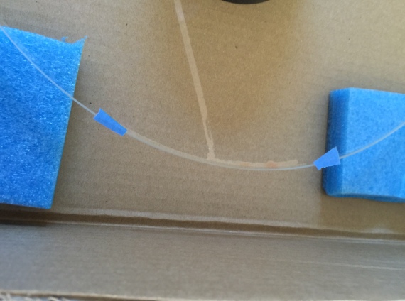
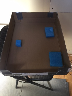
Cut down a cardboard box, taped in a couple of pieces of foam. This will hold the corrector plate when I get it out.


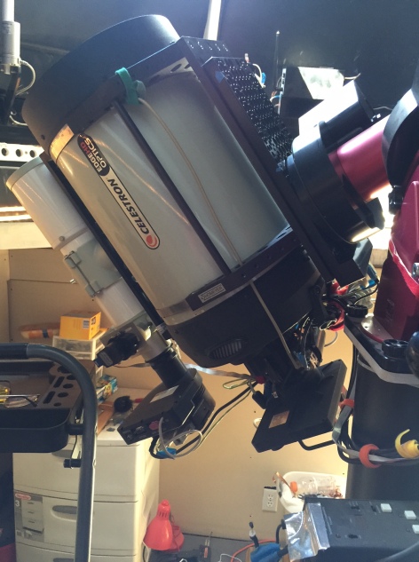
Step 2. Remove the secondary.

Position the scope pointing slightly down and unscrew the secondary.

Am I supposed to remove the holder that holds the secondary?  I don’t see how to do it. After I got everything out I tried again with no success. It seems like it should unscrew into two pieces, but maybe  they are glued together or something. In the end I do my cleaning with the holder remaining in the corrector.

Problem? The secondary holder is loose in the corrector. It spins easily, and moves laterally a millimeter or so in each direction. Is this right?

Step 3. Position the scope with counterweights up, scope pointing up.

IMG_0635

Step 4. Remove the retainer ring.

IMG_0633

The two pieces of tape are cut, allowing me to reposition the retainer ring. This shot also shows the problematic inside streak on the corrector plate.

I don’t know if the positioning of the ring is important. I assume not, but will proceed as if it is:) I put two pieces of blue tape on the ring and tube wall, then cut the tape. The tape pieces will allow me to re-position the ring correctly. Removed 8 screws.

It is tricky getting the ring out. There are two pins sticking out for holding the lens cap. I had to squeeze the ring a bit to get by the pins.

Step 5. Remove Corrector plate.

Marked the plate position with two more pieces of blue tape. Couldn’t find the holding/adjustment nylon pins discussed on CN.

Pulled on the plate (using the plastic secondary holder tube) and it popped out. OK, now I see the nylon adjustment pins I was supposed to loosen.


IMG_0637

Liquid pooled under the corrector plate at upper right of photo.

Danger, Will Robinson! OK, this is weird. There is liquid in two places on the corrector plate edges, and on the corresponding support ring. The liquid is clear but kind of oily/viscous. I have no idea what this is, but I’m pretty sure it is the same stuff that left the trails on the corrector and the tube.


IMG_0642

Liquid pooled on edge of corrector plate, connected to trail across plate

Remote Possibility: Several months ago (4-6?) I cleaned the corrector plate. I used a solution of isopropyl alcohol and water, applied with cotton balls. I suppose it is possible that some of the solution slipped past the corrector. However, I can’t imagine a) there was enough solution to run like this, and b) how could iso and water not evaporate in the Arizona over multiple months?


Step 6. Clean inside of tube?

Tried to clean the specks on the interior of the tube. I’m afraid of messing up the tube, so in the end I left the inside alone.

Step 7. Cover opening with Saran Wrap.

IMG_0641To prevent dust blowing into the tube while I work on the corrector, I covered the OTA opening with Saran Wrap. The wrap doesn’t stick to the OTA like I expected, so more blue tape to hold the wrap in place.


Cleaning the Corrector

I followed the steps laid out by Clay Sherrod at Arkansas Sky Observatory. Assembled all the solutions, filtered, mixed… Got some rubber gloves to handle the corrector so I don’t get fingerprints on it; oops, the gloves themselves leave prints. I end up handling it by the secondary holder that I could never get out.

The tracks on the corrector plate are mostly removed. If I breath on the plate I can still see them, but otherwise they are gone.

Cleaned the outside face of the corrector as well. There are very small spots which I cannot get off. Tried a variety of things with little effect. Sometimes I could get one, but not often. They are hard to see anyway. Oh Well.

Reassembly

Put everything back together, no problems. When putting the plate back in, I loosened two of the nylon alignment pins precisely 1/4 turn. This allowed the plate to pop back in, after which I tightened back the 1/4 turn.

Collimation

Hurray – more problems. First, the secondary still rotates easily and moves laterally. I had hoped that putting the secondary back in would tighten things down somehow. Did it do this before and I never noticed?

Second, I cannot get it to collimate. The stars are huge donuts. Adjusting the screws as usual ends up with one of the screws being completely tightened. Of course that one needs to be tightened more.

I think I have not assembled the secondary correctly? I will need to talk to Celestron and see if they can help.

Electroluminescent Flats

IMG_0622

I have been using Sky Flats in ACP for some time. They work well, but have a couple of procedural limitations:

  • I can’t always be in a position where I can kick them off at a reasonable time. I forget, then it is too late/dark to start them. I suppose I could a) start early in the day, but I don’t like the idea of the observatory sitting open all day, or b) play with the #waituntil command, although I don’t think it actually affects taking the flats.
  • There isn’t enough time to get all my filters in. I do 25 frames for each of 6 filters (R,G,B,Ha,Oiii,Sii). By the time it gets dark enough to begin taking the frames, there isn’t enough time to do all the filters. So, I have to manually edit the flat plan file for the flats I plan to use that night. Of course, I tend to mess that up, or later want to change my mind..

So, I would like to do panel flats. I have played around several times with a flat panel screen mounted on the dome. It works OK, but has problems: 1) the small dome means the panel is not perpendicular to the OTA, 2) I don’t have a way to adjust the light levels for the various filters. For example, the HAlpha filter needs a brighter light than the RGB. I have played quite a bit with different lamps illuminating the screen, but it has never worked well.

I recently ran across a post somewhere (This site is similar to the site I found) that talked about using an electroluminescent panel from Knema.com. I have looked at EL panels before, but they are pretty expensive. This panel was not as much, cost about $200.

To mount my panel I simply cut a hole in the cardboard shipping material. The cardboard folds nicely around the panel to protect it. Velcro strips hold the panel to the shelf.

IMG_0623
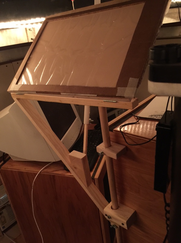
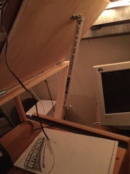
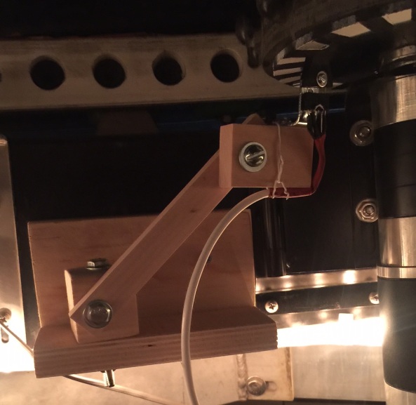
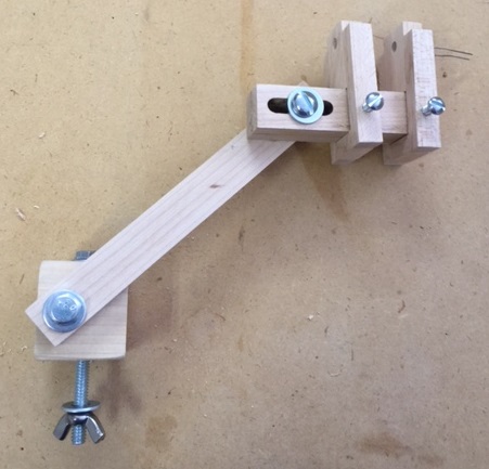
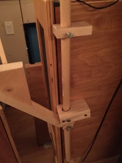
I built a “shelf” to hold my panel. The shelf is adjustable so I can position it about an inch from the OTA, fairly perpendicular.The shelf swings back and forth on the long rod, and slides up and down.


The shelf angle is adjusted with the 1/2 inch PVC arm which slides up and down a wood rod which fits inside the pipe.IMG_0624

The shelf stays in position all the time; as the OTA swings around it does not hit the panel. When I take flats, the OTA swings into position. As it does, it misses the panel by about 1/4 inch. The back end of the scope (camera) also misses the panel.

The panel includes a little inverter box with a knob that varies the brightness of the panel. Originally I intended to replace the knob with a computer controlled potentiometer to adjust the intensity. However, it turns out that all the filters work when the intensity is all the way up. The only exception is the Luminous filter. If I want to do Luminous flats I need to manually turn the knob down to the minimum setting.

Note that HAlpha and Sii flats require long exposures (50-70 seconds). The panel is not white, but heavy in the blue and green spectrum.

In operation the panel power supply wall wart is plugged into my DigiLogger power supply. The ACP AutoFlatConfig file allows turning on the power when the flats are run and turning it off when done.

I can now run automatic flats anytime, except for Luminous which require me to manually adjust the panel intensity down.

Dome Position Sensor for BrewSpinDome

I am busy building a dome controller to replace the Foster Systems unit. I call it BrewSpinDome, an Arduino based controller with a more precise position sensor (2 to 3 times more precise). I use the existing Home sensor.

Mark I Position Sensor

In my first attempt, I used an IR reflective sensor from Adafruit. It has an infrared emitting LED and a phototransistor (photodiode?) to detect reflected light. The two pieces are tilted slightly; the presence of a dark or light spot in front of the sensor changes the output voltage.

The images below show the sensor wheel mounted below the dome rotation gear, with the sensor positioned to detect the dark and white zones. The mounting bracket allows positioning of the sensor precisely under the wheel. It turns out the sensor works best when it is roughly 5mm from the wheel.

MarkIWheel

Looking at the bottom of the dome gear, showing the sensor wheel. The IR position sensor is to the left, aligned to detect the white and black blocks.

MarkIGap

Showing the gap between the sensor and the wheel.

MarkIBracket

The mounting bracket allows several rotations to position the sensor.A header shield is used as the cable connector.

An oscilloscope shows the sensor output as the blue line. The yellow trace shows the Arduino receiving interrupts when the sensor switches states.

ALLBUSY

This was working OK; I used this system to start debugging the software. However, I began to see problems; the dome was missing sensor ticks. It turns out the dome gear “wobbles” a bit as it turns. This moves the gear closer to the sensor, so the voltages are not sufficient to get the pulses shown above.

So, back to the drawing board.

Mark II Position Sensor

In this design, I have a toothed wheel under the dome gear. I obtained an IR LED / phototransistor pair from Radio Shack which are positioned so the toothed wheel breaks the beam as it rotates. Hopefully this will generate better pulses.

MarkIIPail

Plastic pail showing bottom cut off and transformed into the toothed wheel.

The toothed wheel was created by cutting the bottom of a plastic pail obtained from my standard parts warehouse (Dollar Store). The image shows the original pail on top of the bottom piece which was cut off. I used a Dremel to cut the teeth in the wheel, as well as a central hole and two cuts to facilitate placing the wheel around the axle of the dome gear.

MarkIIWheelB.JPG

Toothed wheel after cutting teeth with Dremel. The wheel is cut into two pieces to allow attachment around the Rotation motor shaft. 

I also modified the mounting bracket as shown to place the IR emitter/detector on either side of the teeth. The two LED holders may be adjusted to get the sensor aligned.

MarkIIBracket.JPG

The new bracket. The sensor LEDs are glued into the holes at the upper right (you can see the leads of one LED at the upper right). The two LED holders may be moved laterally to position the sensor correctly between the teeth.

Schmitt Trigger

I also stumbled upon a device known as a Schmitt Trigger, or Schmitt Inverter. It takes my slow-changing pulses and changes them into sharper square pulses. Very nice! I will add this to my circuit. In the Mark I, I was getting multiple interrupts at each transition; I had to add software logic to ignore interrupts for 25-50 milliseconds after receiving one. Maybe this will eliminate that problem.

SchmittTrigger.jpg

I can buy a Schmitt Trigger IC (74LS14) or implement the logic with a 555 Timer as shown in this circuit.


Shutter Fixed?

The continuing saga of the shutter controller…

In the process of testing capacitors on my controller, I somehow managed to plug power in backwards. Thought I had fried everything (Arduino Mega 2560, cc3000, and MonsterMoto shield). In the end, it turns out all that fried was the SWADJ3 voltage regulator.

So, I rebuilt the small PC board to account for a couple of changes:

  1. Added a couple of diodes to protect from idiots plugging in power backwards. The Arduino power branch has a regular N4001 diode; that path shouldn’t be seeing a lot of current. The other diode is a Power diode, handles 50A at 200V or something. Big thing, 3/4 inch square.
  2. Added headers to allow connection to SWADJ3, capacitor, switch input wires. This should allow changing things without having to unsolder wires.
  3. Added capability to add 2 capacitors after the voltage regulator, so I can play with trying to fix the original problem.

I also changed the controller logic to remove the ramping up of the PWM for the motors. I just apply full voltage to the motors.

The new schematic and wiring diagram are here:

Schematic. Dummy board used for MonsterMoto shield.

Schematic. Dummy board used for MonsterMoto shield.

Wiring layout

Wiring layout

The Problem (Review)

The problem I am chasing: when the shutter motors are activated the overall voltage in the system plummets drastically as shown in the data below. The upper shutter doesn’t drop quite as much. Opening the lower shutter is worse than the upper shutter, but is OK (system doesn’t seem to fail). However, closing the lower shutter drops the voltage the most. Sometimes, this drop causes the Arduino to reboot, so the shutter never moves.

Oddly, running the voltage directly into the controller does not lead to as large a voltage drop, so generally the shutter does not fail. However, running the power in through the contact junction causes a bigger voltage drop, leading to frequent failures. I don’t know why this is. I measured the resistance of the junction: 0.7 ohms through the red wire, 1.1 ohms through the black side.

Voltage drops measured after the SWADJ3 voltage regulator.

Voltage drops measured after the SWADJ3 voltage regulator.

Solution?

I tried a variety of capacitors before the regulator and after the regulator. As seen above, none of these seemed to help. In particular, running through the junction contacts causes a very large voltage drop.

In discussions on the SAC forum, it was suggested that my capacitors may be too old. OK, they are probably 30-40 years old… So I went to Radio Shack and picked up a couple of new ones. For power applied directly to the controller, the effect was dramatic! A small blip could be seen, but nothing like the previous situation.

Unfortunately, running power through the junction contacts is better, but still pretty severe. I am concerned that as the dome rotates the contacts may have better or worse contact, still leading to intermittent problems.

I cleaned the copper surfaces, and re-fastened one of the connecting cables to try and improve the connectivity. This helped a little bit. Now the voltage drop is not as severe – it is not going below 5 volts, at least.

Future Possibilities

I am hoping that these changes will allow the shutter to operate successfully. If the problem continues, the following options might be useful.

  1. Maybe I should adjust the SWADJ3 regulator to a higher voltage. I currently have it at 7.2 volts; perhaps if I run it up to 8.0 volts this will raise the dropped voltage the corresponding amount. This leads to more heat dissipated in the Arduino, but perhaps that is not a problem.
  2. Maybe I should experiment with moving the 470 uF capacitor back before the regulator. Forum members have suggested both cases, before and after the regulator. I don’t know why one or the other would be better.
  3. If I understood why the junction causes a problem, perhaps I could redesign it to fix it.

Thoughts on Junction Voltage Loss

The Arduino typically pulls less than 200 mA in normal mode – motors not running, checking for communications every second. In this mode, a 2 Ohm resistance in the junction would give a 0.4 volt drop. Thus, the input 12.8 Volts might be dropped to 12.4 V. This voltage would be constant, and the regulator would easily drop it to 7.2V for the Arduino.

However, when the motor kicks in it pulls perhaps 3-4 amps? 4 Amps would give an 8V drop, leaving only 4 V going into the regulator. It sounds like I need to redesign the junction with much less resistance…

Changes for the shutter

The shutter is still having trouble closing. Opening is always fine, but sometimes the close operation fails. The lower shutter gets power, but never moves. The Arduino goes into reboot mode, as though power was re-applied to it.

My theory is that firing up the motors maybe causes a momentary power surge / voltage drop, so the Arduino thinks power has been cycled. Perhaps the shutter in the closed position requires more power/torque from the motor to get started, due to the angle of the activator pulling the shutter closed.

Connecting power directly to the shutter (bypassing the “brush/ring” mechanism) works.

Things to try:

  • Perhaps the copper tape on the track, used to distribute power to the Arduino, is torn or worn. I replaced the tape in the park position area. The brush/tape system now has a resistance of around 5-10 ohms.
  • I notice that the shutter failure occurs when the park position does not place the dome in the exact correct spot. The Foster is often off by 6-12 inches when it parks the dome. In fact, I am seeing potential problem here – sometimes the position is 3 feet off! Oh, boy, another Foster problem to debug.

On the other hand, the home sensor is fairly accurate since it works by detecting the sensor magnet. It will be a couple of inches off depending on which direction the dome turned to find home, but it is consistent. So, I moved the home sensor so that home is in the same position as park. Foster version 3.2.3 has a checkbox that indicates Home is the same as park, but Parking does not use the magnet. It just goes to where it thinks the home sensor should be; this position can be off several inches.

Incidentally, the inaccurate positioning started happening with version 3.2.2. Updated software/firmware to 3.2.3, same problem.

I re-synced the telescope so the rotation is consistent with the new home sensor position.

  • I changed the Arduino code to ramp the pulse width modulation (PWM) from 512 (doesn’t move the motor) up to 1023 (full speed) in steps of 64 every 50 msec. I thought maybe this would help avoid the power drop. I can hear a slight change in the motors starting up.
  • If these things don’t work, my last idea is to install 2 large capacitors on the the Sparkfun MonsterMotor board. They leave spots on the board for these capacitors, but I can’t get any information from them on what they are for or how one would size them. Maybe these capacitors would avoid the power drop. If one even exists:)