NOTICE
This site has moved to the new URL here.
Thank you

My observatory is in the Arizona desert. As such we get a tremendous amount of dust in the air.
I spent 4 days cleaning the observatory. The dust is tough to get up; it is thick and deposits like mud (probably electrostatically charged). You can’t use a Swiffer or dust cloth – at best that just smears the dust around. You have to use rags and water to pick it up.
I have implemented some anti-dust strategies which I hope will help:
Have obtained a new-to-me FSQ106EDIII. After some false starts I have the adapters from OPT and Texas Nautical. Built another bracket to attach the EZFocus motor.
While testing the focuser for slippage the wall wart died. Very hot, no voltage. Replaced it with a cable to the old 12V power supply, seems to be working now.
Odd issue – while running the VCurves and ACP Focus Offset script, I notice that the focus position seems to be consistently changing. If I run multiple focus runs in a row, as quickly as possible, the resulting position seems to shift by about 35-40 focuser tics. This shift is probably roughly the size of the crtical focus zone.
So, when Focus Offsets runs, it seems like the focus position of each filter is off by n*35 tics. When HAlpha comes up with an offset of 189 tics, it may actually be off by 140 tics!
I don’t know what is causing this shift. The scope certainly doesn’t shift temperature that fast. I thought maybe the focuser was slipping, but measuring the position of the camera with a dial caliper shows to slippage. I ran the focuser back and forth 5 times (1000 pulses each way) and it ended up back at the correct position each time.
I did find that the backlash was off; I changed from 200 to 500 pulses. I will re-run the Focus Offset script again.
Updated ACP to 8.1, including updating the web system.Cleaned up the web menu system a bit, added a couple of items (AstroCalc).
Updated FM to 4.1.0.44.
Playing with Drizzle again.
Saw a mention on the PixInsight forums about Drizzling with factor 1. Apparently this can help reduce the noise in your stacked image? Odd idea, I will have to try that sometime.
Tried varying the drizzle Kernel function. There are several possibilities, primarily Square (default), circular, and Gaussian. Potentially Gaussian can provide better results, but needs a larger number of subs to work well.
So, I tried doing 16 subs (Blue filter of M100, binned x2, 15 minutes each), using each of the 3 functions. I used a 0.9 drop size for each, drizzling by a factor of 2. The hardware was the STF8300M / Edge 11 combination. Measured the noise of the integrated image using the Noise script.
| Kernel | Noise (e-4) |
| No Drizzling | 2.590 |
| Square | 1.511 |
| Circle | 2.015 |
| Gaussian | 2.580 |
Clearly in this case the default Square function performed the best. The Gaussian took significantly longer to calculate and was no better than not drizzling at all..
In the course of chasing down a weird problem, a couple of issues came up in discussions with other people.
I.e., do I need separate Bias Masters at each temperature, or does one master work at all temperatures? Maxim is clearly set up to use different temperatures.
I generated Bias Masters at several temperatures from 0C down to -13.5C. This was as low as I could go, since Arizona is still too warm for the camera to get any cooler. Forty subs were taken directly in Maxim and converted to the Bias Master in Maxim using the SD Mask combine of 40 subs. The subs were taken after the new temperature set point appeared to be stable (roughly 20-30 seconds after the set point was reached). I ran a couple of them twice to see how much variation might be seen from run to run. Also, I have a couple of older masters (1-2 years old) at -15C and -20C.
For each master I measured the median intensity at the center of the image using Maxim’s Information tool with the biggest aperture available (20 pixels).

It seems clear that the recently built masters are the same out to -13.5C. The colder ones are likely too old, which is why they are different. I would not expect some dramatic shift from -13.5C to -15C.
In discussions with Joe Mize (he has had a number of interesting points!), he pointed out that he waits a couple of hours for the CCD to stabilize before taking Bias frames (he calls this “cold soaking”).
As a typical impatient person, I generally set the cooling target, set up the AutoSave sequence to take the desired Bias and Dark frames, then start the imaging. The Bias subs are taken first, for no particular reason. As the temperature approaches the set point the temperature typically oscillates a bit around the set point as the system control settles. This usually happens for 15-30 seconds. Once the cooling target appears to be stable I start the AutoSave acquisition.
Now Joe indicates I need to wait a couple of hours:(
So, I did a couple of runs. Run 1: I set the cooling point to -10C, waited as usual for the temperature to settle, and took a set of 40 Bias subs. These were combined into a master in Maxim’s Set Calibration tool using SD Mask median combination. I then used the Graph Information tool to draw a horizontal line in the exact center of the image.
After 30 minutes I took another set of 40 subs and created another master. I repeated this process at 1 hour and 1.5 hours. The following animated gif flips among the resultant graphs. The red text at the upper right indicates the elapsed time before creating the master.
It appears that the initial master is in fact somewhat lower than the subsequent graphs by 32 counts (about 1.5%). After 30 minutes the graphs seem to be relatively consistent. So, it looks like I do in fact need to wait perhaps 30 minutes.
Run 2: I turned the system off for about three hours, then repeated the test. This time I created a master every 5 minutes in order to get a better estimate of when it has stabilized.
I should have changed the label at the top; 1 is the first master, 2 is after 5 minutes, 3 is after 10 minutes, etc. It looks like by 10-15 minutes the masters have equilibrated.There is less of a shift (15 counts, or 0.75%); perhaps the system didn’t completely warm up from the previous test.
So, it looks like I should let the system cool for 15-30 minutes before starting the Bias frames.
I might expect the same effect when taking darks. However I expect the issue to be less noticeable since the subs are typically 15 minutes or so; the first sub might be off but subsequent subs should be equilibrated. There might be an effect if doing short subs like 1 minute.
I was reading an interesting article Signal to Noise: Part 3 – Measuring your Camera by Craig Stark. I thought it would be fun to go through the exercise of measuring the various characteristics of my STF8300M.
One of the checks is this very topic – how long does it take your camera to cool to a stable temperature? His approach is to turn on the cooler, then start taking 1 minute dark frames. He expects to see a pattern in the beginning followed by a steady state dark median after some time.
In my case, the camera reached the target within 1 minute! Only the first dark showed any significant difference while the camera cooled.

I have always used single star guiding in Maxim. However, in Maxim version 6 they implemented multi-star guiding. I wanted to test the multi-star compared to the usual single star.
Basic conclusion: multi-star guiding does not show an appreciable gain in guiding precision. There may be other reasons for using it; perhaps it is more robust somehow, perhaps it is better in poor seeing conditions? I was unable to test these issues; I just looked at guiding precision.
The clear difference in guiding was better seeing as the night went on. The initial guiding started after astronomical twilight. Both guiding techniques improved significantly as the evening went on. I often see this trend when using the Subframe Selection script in PixInsight; as the evening wears on the FWHM moves steadily downward.
I imaged several 5 minute exposures, binned 2×2, using the Edge 11/STF8300M setup. The guider is the integrated STi in the 8300 package. This setup has an image scale of 0.80 arcseconds per pixel.The STi is binned 1×1. The same calibration settings were used for Single star and Multi-star guiding.
The images were well guided; I happened to have better seeing this night. In poorer seeing I typically see larger fluctuations in the guide errors. It may be that multi-star guiding would help more in poor seeing.
I used three targets: one in the Milky way to ensure a good number of guide stars for multi-star guiding, and two targets with few guide stars. The images are not calibrated or stacked, although the Maxim Filter tool was used to remove hot and cold pixels.
I measured the guiding accuracy using the graph tool in Maxim. After guiding has been started I clear the graph and let it run for 30-50 points. I then read the RMS X and Y errors from the graph, clear the graph, and repeat. In each situation (single or multi star guiding, a particular target) I repeat this process 5 times and average the results.
I also measured the FWHM of the resulting images using both CCDInspector and PixInsight. Their results were essentially the same, which is reassuring.
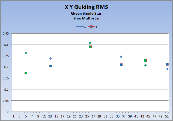
This shows the RMS guiding error as the evening went on. The green points are using single star guiding, the blue use multi-star.
In the first half of the graph the RMS errors are more variable. In the second set of three readings the guiding has settled into a more consistent pattern.
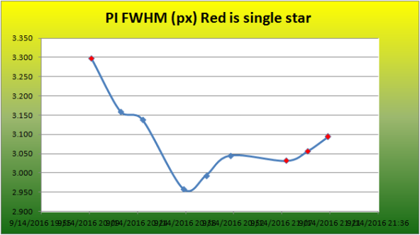
These are the FWHM measurements from PixInsight (in pixels). The first image in particular was poorer (3.3 px * 0.8 as/px = 2.64 as. The last six images are around 2.4 arcseconds.
I installed a small 8000 BTU window air conditioner in the dome several years ago to keep the dome cool during the summer. I am concerned about the dome getting so hot in our 115 degree heat that the electronics will be damaged (computer, power controller, mount, …).
As described in an earlier entry, I built an Arduino based temperature probe and wrote a little program ACCycle to turn the air conditioner on and off.

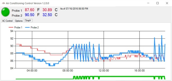
This has been working OK, but the AC is clearly unable to keep up. As the image above shows, no air conditioning would generate the red line. The orange line shows the typical response to the single unit coming on; it lowers the temperature in the dome by 5-10 degrees, but otherwise follows the ambient.
So, I bought a second 8000 BTU unit. This one is a portable unit with the big hose that exhausts out the window. The blue data shows the result of both units turning on – the temperature immediately lowers back to the target 85 degrees.
First, it is clear that the two units together work very well. Now, instead of seeing the dome temperature follow the outside temperature (but a few degrees cooler) I can see the AC units kicking in and bringing the temperature back down to 87. I have it set to start cooling at 90, stop at 87. In the image below the dome temperature (blue line) rises steadily in the morning. About 8:30 it hits the upper limit of 90, at which point the two units kick on. They quickly cool back below 87, at which time they shut off. The units cycle until about noon; at that point the heat is enough that the units stay on steadily until about 5:00 PM, when it starts cycling again.
But – I am encountering power problems, which I have never had to think about before.
To start, my Power Controller is plugged into a big surge protector, which in turn is plugged into the wall. When the two AC units are turned on, the power exceeds the surge protector limit. The surge protector shuts off, including power to the computer and everything. I have to reboot the system and start everything again. Doesn’t happen every time, so I am apparently close to the limit of the surge protector.
So, my next step is to plug the power controller directly into the wall, bypassing the surge protector. In addition, the controller has an “A” and “B” side, each allowing 15 amps. I had been running both AC units from one power cord on the “B” side. Now I plug one AC into the “A” side and the other into the “B” side.
Well, it is better, but every so often ACCycle turns the AC on but they don’t actually turn on! I think the surge through the Power Controller is problematic somehow. I have trouble reproducing the problem, but is seems to happen a couple of times a day. Unfortunately, it can end up in a state where the AC is off, but ACCycle thinks it is on. Thus, the dome keeps heating up.
Next approach – get around having both units turning on simultaneously.
One approach would be to put the two units on separate ports in the Power Controller and have ACCycle control both units. However, I don’t have any extra ports in the Power Controller. I could buy another controller:(
Instead, I put one unit on a manual timer on the wall socket. This timer will turn on the AC at 9:30 in the morning and turn off at 7:30 at night, after sundown. At this time of year there aren’t any days where cooling isn’t needed, so this is reasonable.
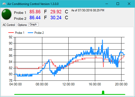
Now ACCycle only controls the second unit. It only kicks in when the first unit cannot handle the load. Both units don’t necessarily run, and they don’t kick on at the same time. In the image below the first unit started at 9:00 AM. It was a cooler day (only reached 101) so the second unit wasn’t needed until late in the day about 4:30 PM. It kicked in briefly when the temperature got above 90 and quickly brought it under 85, at which point it wasn’t needed any more.
I have been wondering about the effect of the full Moon’s light on images. In particular, there is a tempting thought that if your target is far enough from the Moon in the sky, perhaps the Moon’s effect would be negligible. Also, I noticed something in ACP Scheduler that sounded like you might be able to image at angles greater than 120 degrees from the Moon. Since we are having a full moon now, I thought I could try a simple test and see what happens.
I set up an ACP plan to take images every hour through the night. Each hour, ACP would:
a) Focus the Edge 11
b) Take 3 one minute unguided images at a position 60 degrees altitude to the SouthEast using the Luminous (Clear) filter. These images are at some angle from the moon, as given by theSkyX. This target point yielded images at angles of 23 to 55 degrees from the Moon.
c) Take 3 more one minute unguided images using the OIII filter
d) Take 3 more images at a second target position to the NorthWest, again at 60 degrees altitude. The second position was simply to give me points at a greater angle from the moon; I got angles of 75 to 115 degrees from the moon. This target is in the Phoenix light dome so I expect to get higher counts.
e) Take 3 more images with the OIII filter.
f) ACP then sleeps until the next hour is up, at which point the steps above are repeated.
Since my images are at a set Altitude/Azimuth, the images produced are different for every hour. The contents of the images are irrelevant – all I am interested in is the background count.
The Moon rose at 10:43 at 85% illumination. The first set of images were taken at 10:00 PM while the Moon was till down, so that should give a “zero point” for comparison. At this time the Moon was 9 degrees below the horizon.
I used CCDInspector to retrieve the background and contrast for each image, then averaged these values for the three images at each point/filter. Some of the OIII images did not report a contrast, presumably because there were no stars really visible in the image.
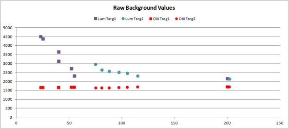
Figure 1. Raw Background counts as a function of angle from the Moon.
The graph shows the effect of the Moon’s angle on the background counts of the raw Luminous and OIII images.
In the Luminous images there is a clear trend toward less background as the angle from the moon is increased. The values at 200 degrees are those produced when the Moon had not yet risen. It seems clear that the Moon’s effect is in fact negligible once the angle gets to 120 or so. Logistically it may be difficult to this large an angle between the Moon and target. Perhaps some Northern targets could be imaged when the Moon is to the South.
I am surprised at the OIII results. It appears that the OIII background does not depend on the Moon’s angle. Even when the moon is not yet up the background is the same. However, I have previously determined that the Moon scatters a significant amount of OIII light when it is up. Perhaps the Moon was close enough to the horizon to scatter a lot of OIII? I do not understand this result.

Figure 2. Effect of the full Moon on calibrated image background values.
Calibration is performed by Maxim using Bias, Dark, and Flat frames. I had anticipated that the calibrated results would follow the same pattern as the Raw data. As seen in the graph, this is roughly true for the Luminous images. The points in the Phoenix light dome (blue triangles) have higher values, but they are dropping toward the zero point. 120 degrees may not be sufficient to approach the no-Moon case.
However, the OIII results are all over the map. Most of them are at a constant level, but some of the points have very large backgrounds after calibration. Again, I do not understand this variability.
It turns out that the contrast measured by CCDInspector depends on the contents of the image. If there are a lot of stars or structure the contrast will be higher. This is fine when comparing images of the same target; a higher contrast in this case indicates a better image. However, in this data the contrast readings are random since the image field is different at each point (I am keeping the image at 60 deg Altitude and a fixed Azimuth).
It is not worth it. When the Moon is up, there is still significant light in the calibrated images out to angles of 150 degrees. It may be possible to do something with narrowband filters, but the data there is confusing.
Stay with imaging when the Moon is down.
The saga comes to a close…
After talking to the Celestron Rep (Will) it sounds like I missed something when inserting the secondary. There is a small set screw on the inside of the secondary which needs to fit into the slot on the secondary housing (the tube passing through the corrector plate).
Will also made a couple of other points.
I retried inserting the secondary, making sure the set screw is positioned correctly. It seems to fit better.
Voila! Now I can focus correctly. I then worked on collimating, and was able to make that work.
I then tried the collimation tool in CCDInspector; I’ve owned this tool for awhile but never tried this piece. It was a little confusing at first. There are various colors which I anticipated were trying to tell me stuff, like which direction to turn the screw – apparently not.
One very helpful aspect – I connected Maxim to the ACP Telescope hub and put in the correct image scale (0.39″/px). This enables the function in the right click menu on an image to re-position the scope to point to a particular spot. This makes it much easier to recenter the scope after each adjustment.
After I got the hang of it, I was able to get the collimation to less than 5″, perhaps under 3. At that point the seeing and clouds were preventing any improvement. The collimation is clearly better than what I used to get using my manual method. A focusing run shows very symmetric patterns on the stars.
Now that I am correctly inserting the secondary, I still need to get the secondary housing firmly attached to the corrector plate. Before starting with Will’s suggestions I called Dean at Starizona to get his thoughts. He had some other techniques I could try to tighten the housing.
In the end, I decided to bring the OTA to Starizona rather than risking messing up the housing. I’m glad I did. Dean was very helpful and knowledgeable. It was great just seeing him do some of the various tasks – there are a lot of things one hears about, and that I have done, but don’t really know how to do exactly.
Dean pulled the corrector and managed to get the two parts of the housing separated. He then replaced the paper (almost invisible) gaskets with a rubber type, then re-installed the housing in the plate.
He then cleaned the corrector, doing a much better job than I had. Very interesting watching his technique.
Now came a possibly controversial part. There are several threads out there about whether the corrector should be moved. In particular, a long series of posts on Cloudy Nights which concludes that the plate should not be moved from the factory setting, and should not be physically centered (the factory setting is the correct optical centered position). Dean disagrees – after putting the corrector back in, he adjusted the position to get the secondary/housing/corrector centered by looking down the OTA from 6-12 feet. He says he has convinced Celestron they are aligning their correctors incorrectly? They came out and visited to see how he does it…
Also, Dean positions the secondary and housing to point at 3 o’clock instead of 1 o’clock.
Anyway, he did his alignment which included very slightly shifting the corrector. He also collimated using an artificial star. He clearly has a very experienced eye.
The source of the trails on the corrector was identified by Dean. Apparently when it gets hot the grease on the primary baffle can bleed some of the more volatile components. Dean showed me the trail running down the primary baffle; clearly the same fluid on the corrector plate and under the edges of the plate.
I have (cleverly, I thought) defined the scope’s park position to have the OTA pointing down. The idea was to keep some of the Arizona desert dust from collecting on the corrector plate. This was a bad idea, since it allows the grease to drip onto the corrector.
If the OTA is pointed up, the grease will run down into the back of the OTA. Apparently this is not a problem.
After I got the OTA remounted, rewired, and balanced I was curious to see how Dean’s collimation was, as per the CCDInspector tool. It was pretty good, about 14″. Certainly better than what I would get (about 50-70″). I then played with it and managed to get it to 1.5″. At that point the direction line is flitting around quite a bit, but generally less than 1″. Wow!
Now I have centered the focus position near 3500 on the Optec, locked the mirror down, and started re-running VCurves. I’m eager to see how the overall performance of the system might be affected.
For a little while I have been getting strange diffraction spikes from the Edge 11/STF8300M system, as seen in the sub below. The brighter stars have 2 diffraction spikes, when they should not have any (no support vanes to cause them). The two spikes are at a 10-20 degree angle from each other.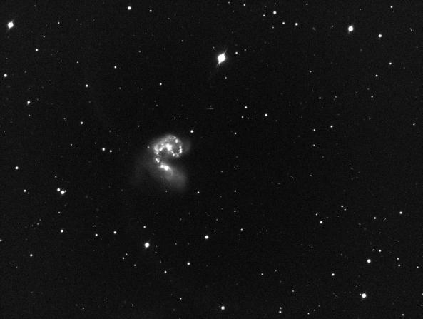
The crop below shows is zoomed in a bit to show the spikes better:

I have been working on my Dome driver for the Arduino controller; I thought these were due to the OTA not pointing accurately out the dome’s slit. However, when I got around to checking, the OTA was in fact pointing precisely out the slit.

Big trails seen on the left. Two trails are at an angle, leading to the observed diffraction spikes.
So, I went out and started to look at possible causes. Right off the bat, when I looked at the corrector plate, there were 2 “trails” on the inside of the corrector plate! It looks like a snail crawled down the plate. The trails are at an angle, matching the angle of the diffraction spikes.
 In addition, there are a couple of trails on the inside of the tube, along with a blotchy area. These look like liquid has somehow run down the tube and dried.
There are also a bunch of small drop “splatters” on the inside of the tube. These are hard to see in the image because the corrector is also fairly dirty on the outside.
So, time for a fun new project – removing the corrector plate and cleaning it. I have seen lots of comments about dangerous this is…
Cloudy Nights had a very good description about removing the plate, although no pictures so I don’t necessarily know what they are referring to.
Step 1. Carrier Box
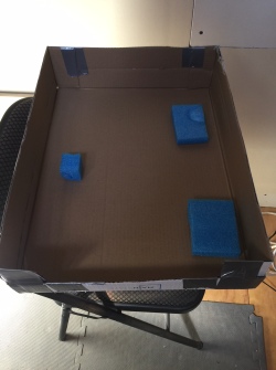 Cut down a cardboard box, taped in a couple of pieces of foam. This will hold the corrector plate when I get it out.
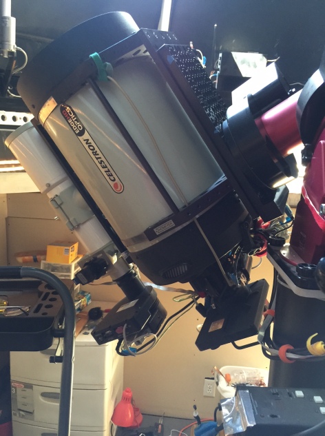
Step 2. Remove the secondary.
Position the scope pointing slightly down and unscrew the secondary.
Am I supposed to remove the holder that holds the secondary? I don’t see how to do it. After I got everything out I tried again with no success. It seems like it should unscrew into two pieces, but maybe they are glued together or something. In the end I do my cleaning with the holder remaining in the corrector.
Problem? The secondary holder is loose in the corrector. It spins easily, and moves laterally a millimeter or so in each direction. Is this right?
Step 3. Position the scope with counterweights up, scope pointing up.
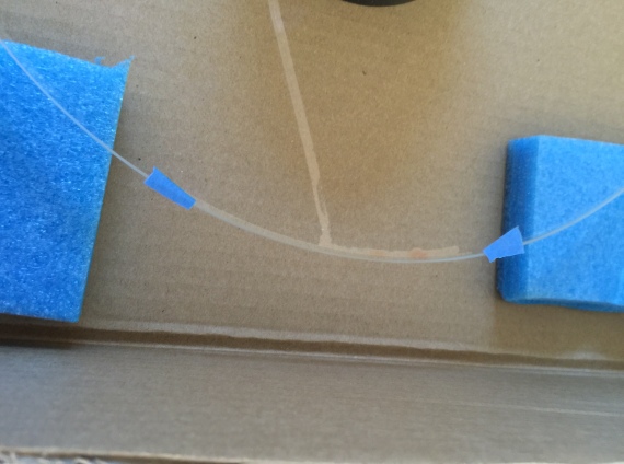
Step 4. Remove the retainer ring.

The two pieces of tape are cut, allowing me to reposition the retainer ring. This shot also shows the problematic inside streak on the corrector plate.
I don’t know if the positioning of the ring is important. I assume not, but will proceed as if it is:) I put two pieces of blue tape on the ring and tube wall, then cut the tape. The tape pieces will allow me to re-position the ring correctly. Removed 8 screws.
It is tricky getting the ring out. There are two pins sticking out for holding the lens cap. I had to squeeze the ring a bit to get by the pins.
Step 5. Remove Corrector plate.
Marked the plate position with two more pieces of blue tape. Couldn’t find the holding/adjustment nylon pins discussed on CN.
Pulled on the plate (using the plastic secondary holder tube) and it popped out. OK, now I see the nylon adjustment pins I was supposed to loosen.

Liquid pooled under the corrector plate at upper right of photo.
Danger, Will Robinson! OK, this is weird. There is liquid in two places on the corrector plate edges, and on the corresponding support ring. The liquid is clear but kind of oily/viscous. I have no idea what this is, but I’m pretty sure it is the same stuff that left the trails on the corrector and the tube.
Liquid pooled on edge of corrector plate, connected to trail across plate
Remote Possibility: Several months ago (4-6?) I cleaned the corrector plate. I used a solution of isopropyl alcohol and water, applied with cotton balls. I suppose it is possible that some of the solution slipped past the corrector. However, I can’t imagine a) there was enough solution to run like this, and b) how could iso and water not evaporate in the Arizona over multiple months?
Step 6. Clean inside of tube?
Tried to clean the specks on the interior of the tube. I’m afraid of messing up the tube, so in the end I left the inside alone.
Step 7. Cover opening with Saran Wrap.
 To prevent dust blowing into the tube while I work on the corrector, I covered the OTA opening with Saran Wrap. The wrap doesn’t stick to the OTA like I expected, so more blue tape to hold the wrap in place.
I followed the steps laid out by Clay Sherrod at Arkansas Sky Observatory. Assembled all the solutions, filtered, mixed… Got some rubber gloves to handle the corrector so I don’t get fingerprints on it; oops, the gloves themselves leave prints. I end up handling it by the secondary holder that I could never get out.
The tracks on the corrector plate are mostly removed. If I breath on the plate I can still see them, but otherwise they are gone.
Cleaned the outside face of the corrector as well. There are very small spots which I cannot get off. Tried a variety of things with little effect. Sometimes I could get one, but not often. They are hard to see anyway. Oh Well.
Put everything back together, no problems. When putting the plate back in, I loosened two of the nylon alignment pins precisely 1/4 turn. This allowed the plate to pop back in, after which I tightened back the 1/4 turn.
Hurray – more problems. First, the secondary still rotates easily and moves laterally. I had hoped that putting the secondary back in would tighten things down somehow. Did it do this before and I never noticed?
Second, I cannot get it to collimate. The stars are huge donuts. Adjusting the screws as usual ends up with one of the screws being completely tightened. Of course that one needs to be tightened more.
I think I have not assembled the secondary correctly? I will need to talk to Celestron and see if they can help.
